How to Make Almost* Anything | MAS.863
Ella Peinovich | M.Arch Level III, MIT
Ella Peinovich | M.Arch Level III, MIT
video test
This short video helps to describe the programming that went into the design of the wall. The code can be found here: Light Sensing Array Code
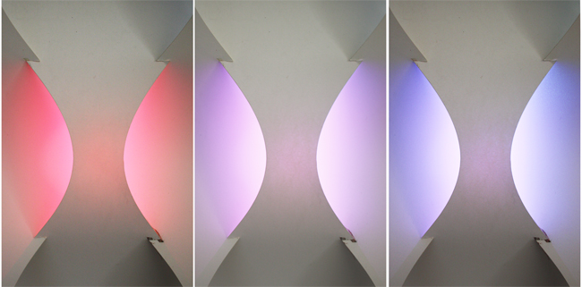
The goal of the light sensor array is to use a series of light sensors on a curved surface to sense the sun at each angle perpendicular to the curve. Sensors placed vertically on a curve are used to gather information about the broader environmental conditions seen by the wall (like time of day or year). A series of LEDs embedded horizontally in an array across the wall sense the more temporal, local conditions (like shadows or weather patterns).
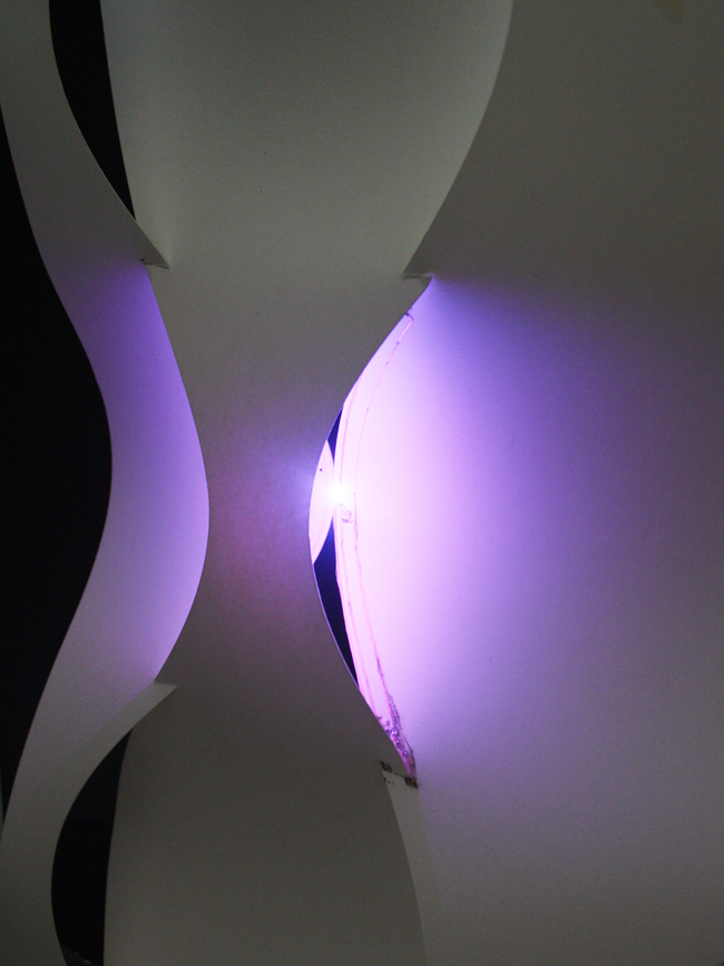
Absense of light on the bottom sensor would suggest that the light is high in the sky, suggesting a day and even summer light condition. Direct light on the bottom sensor would suggest a low light and winter condition. A Red LED turns on when sensing a summer sun angle and the Blue LED turns on when sensing a winter angle. Purple light is displayed during times of indirect lighting, and the value reacts inversely with the light level sensed. A Green LED blinks on if a shadow passes over the sensor on the middle of the panel, sensed by a reduced light capture compared to other nearby sensors.
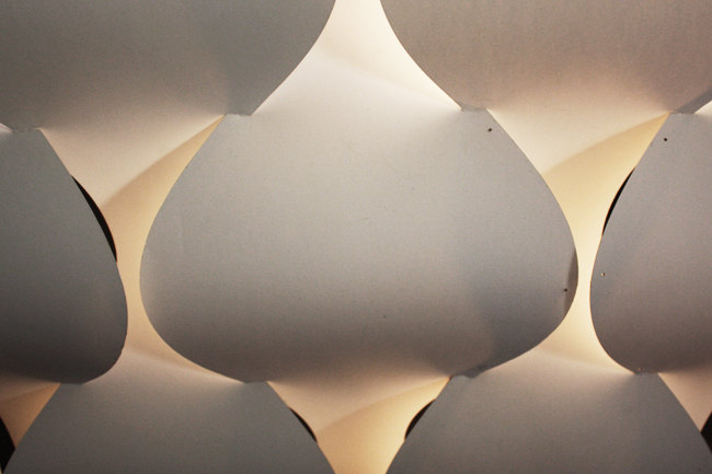
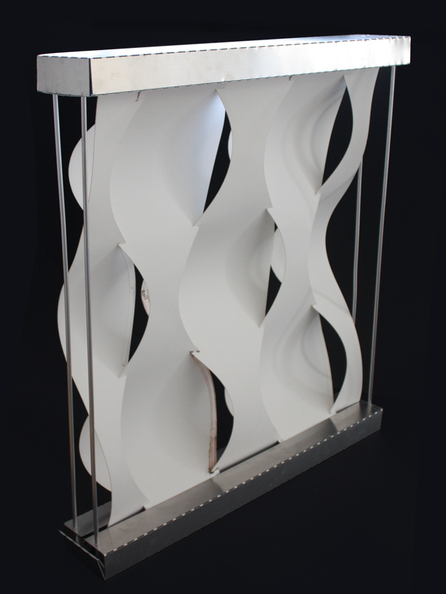
View of wall under ambient light condition
My goal was to create an active wall screen with integerated circuitry. Yet, providing that the wall screen will still look elegent when the technology is inactive.
circuit bridge
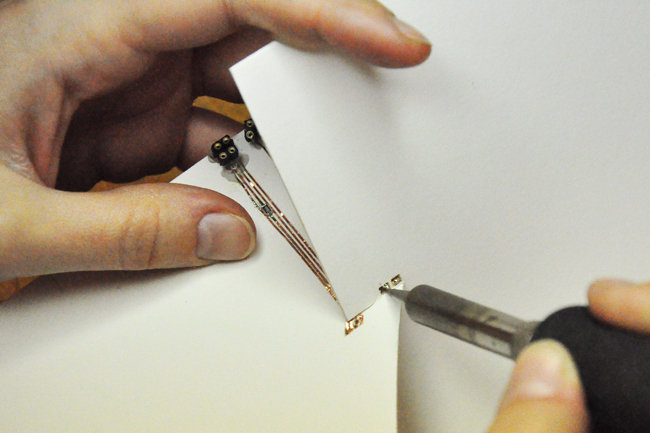
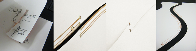
One goal of the design was to develop an example of a circuit integrated into the structural material. I chose to use a vinyl cut circuit in combination with vertical panels of two-ply bristol board cut and scored on the laser cutter. In order to achieve a curved surface assembly that did not require any joinery, the wall is held together through a series of slits that allow for an overlap in the panels, using tension to hold the wall together. The circuit is nestled within the area of overlap as a result of the joinery of the wall elements. Through holes were placed to coordinate with pads on the alternate panel. Notice that the circuit and hardware disappear within the overlap of the seperate panels.
This through-hole, bridged circuit works in theory and would have worked in application if only the adhesive on the vinyl was conductive. I was lead to believe that the adhensive was conductive, but this is only true when under compression. Force must be added to connect the top and bottom traces. Since this option was not possible without adding joinery, I had to use solder to connect the circuit flow.
A foldable, waterjet aluminum base and cap were then cut to hide the fabduino and FTDI cable, while propping the paper screen upright.